
- Home
- »
- Measurement Guide
- »
- Impedance Analyzers Calibration
Comprehensive Calibration Guide for Impedance Analyzers
Step-by-step calibration techniques for Eynocs impedance analyzers. 2-, 3-, and 4-wire configurations, warm-up protocols, and standard verification.
Proper hardware verification and systematic calibration form the cornerstone of accurate dielectric spectroscopy and impedance analysis. Skipping proper initialization or performing calibrations under unstable conditions introduces measurement drift, phase errors, and invalid results.
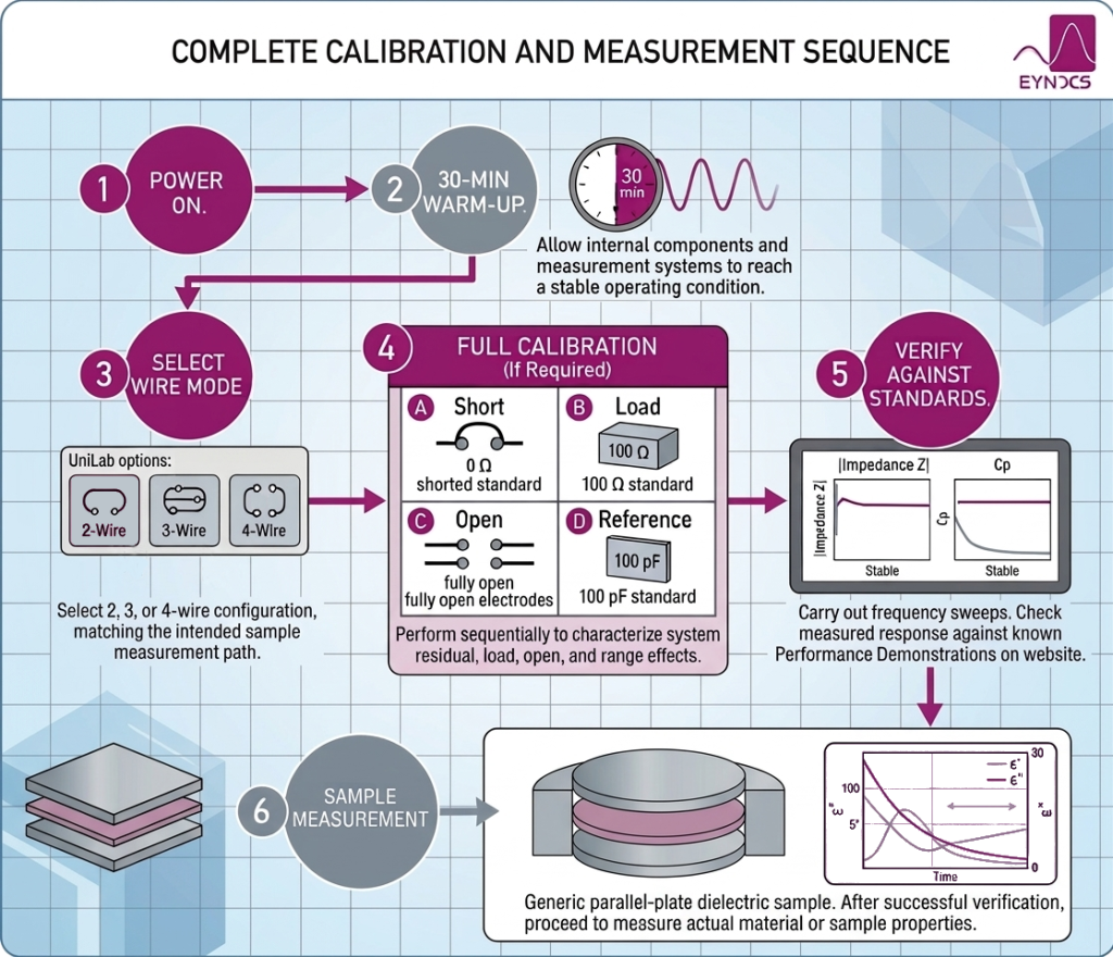
1. Instrument Warm-Up Protocol
Before initiating any calibration routine or performing precision measurements:
- Allow your Eynocs analyzer and interface to warm up for at least 30 minutes.
- Internal analog circuitry, current-to-voltage converters, and signal generators require thermal equilibrium to minimize measurement drift.
- Do not calibrate during warm-up. Performing a calibration while internal components are changing temperature bakes thermal drift into your calibration matrix, skewing subsequent readings.
2. Wire Configuration Selection
You must select and verify your measurement wiring configuration in UniLab prior to calibration.
- 2-Wire Mode: Best suited for standard parallel-plate dielectric measurements where contact impedance is negligible.
- 3-Wire Mode: Provides separate voltage sensing for advanced voltage control relative to current paths.
- 4-Wire Mode: Essential for low-impedance samples, conductive materials, or setups where cable impedance and contact resistance degrade measurement accuracy.
Critical Rule: Always calibrate in the exact wiring configuration (2-, 3-, or 4-wire) that will be used for your sample measurements. Changing wire configurations post-calibration invalidates the calibration data.
3. Step-by-Step Calibration Sequence
Navigate in UniLab to: Measurement Setup -> Preparation Phase -> Analyzer Section -> Analyzer Calibrations.
| Calibration Type | Connection Setup | Purpose & Verification Parameter |
| Short Calibration | Short-circuit cell electrodes or insert Short Standard | Characterizes residual impedance (0 Ω). Verify using a frequency sweep; total impedance |Z| should decrease at lower frequencies. |
| Load Calibration | Connect 100 Ω Load Calibration Standard | Compensates system response against a known load. Verify that |Z| ≈ 100 Ω across the frequency spectrum. |
| Open Calibration | Fully open electrode plates or leave lin/CE open | Compensates for parasitic fixture capacitance (∞ Ω). Verify parallel capacitance Cp stays in the low femtofarad (fF) range. |
| Reference Calibration | Connect 100 pF Reference Standard (or internal Omega reference) | Validates individual measurement ranges. Verify Cp and tan δ against standard limits. |
This information, together with additional practical recommendations and measurement considerations, is covered in the complete guide for optimal measurement conditions with Eynocs Analyzers